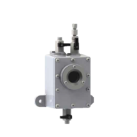
Buchholz Relays
Simple operation, high reliability and a very long life-time characterize our Buchholz relays according to DIN EN 50216-2 as well as IEC 60076-22-1. Find out more about our type deversity.

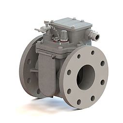
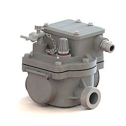
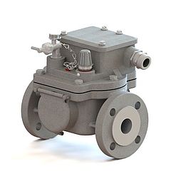
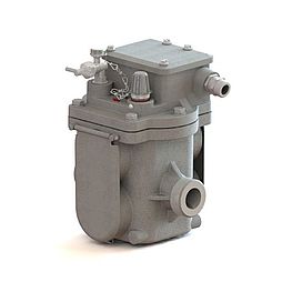
Buchholz Relays
The Buchholz relay was developed in 1921 by Max Buchholz, Oberrat (senior councillor) at Preußische Elektrizitäts-A.G. (Prussian electricity company) in Kassel. Since that time it has been an important protection and monitoring device for insulating liquid filled transformers with conservator and choke coils. It also allows separate monitoring of oil-filled bushings or cable terminal boxes. It is mounted in the cooling cycle of the device to be protected and responds to faults such as gas generation, loss of as well as high flow rates of the insulating liquid.
For transformers with hermetical closure by means of a hydro-type compensator (rubber sack) in the conservator, the Buchholz relay can be used also as monitoring device (air cell failure relay) of the hydro-type compensator.
The Buchholz relay is suitable for open-air as well as indoor installations.
General
The type diversity of the Buchholz relay is tailored to norms and standards as well as to special customer demands. The type of relay to be used depends on the nominal rating and construction features of the device to be protected. Our range of products permits optimum adaptation to actual requirements.
Elektromotoren und Gerätebau GmbH (EMB GmbH) provides more than 70 years experience in producing Buchholz relays and other protective devices for liquid-cooled and liquid-insulated devices. It ranks today among the most distinguished manufacturers of this type of equipment.
EMB Buchholz relays are in compliance with EN 50216-2 as well as IEC 60076-22-1 and are known for their easy operation, high reliability and extremely long life. The functionality of the EMB Buchholz relays is given by using all conventional insulating liquids. The functionality in combination with new insulating fluids will be tested in close cooperation with the manufacturers.
EMB has been certified according to: DIN EN ISO 9001:2015, AEO F, Known Consignor (Airfreight Security) and EAC. Further certifications have been awarded by well-known independent test laboratories such as TÜV Rheinland and TZO.
Design Features
Casing
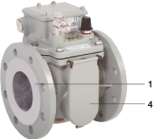
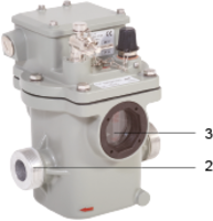
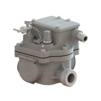
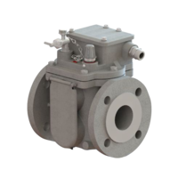
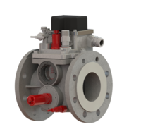
The casing is made of weather-resistant cast aluminium alloy provided with a paint coating. It is supplied either with flanged (Fig. 1/ Number 1) or threaded connection (Fig. 2/ No.2). The different casing designs available are shown in Single-Float Buchholz Relays and Double-Float Buchholz Relays. Others are available on request.
To check the switching system for proper function, the casing is provided with sightglasses (Fig. 2/ No. 3). The sightglasses provided with scales permit reading of collected gas volume. The relays can be provided with hinged lids (Fig. 1/ No.4) to protect the sightglasses.
Cover
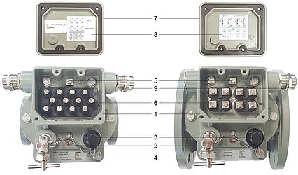
The cover is made of weather-resistant cast aluminium alloy provided with a paint coating. The upper section of the cover accommodates the terminal box (Fig. 3/ No. 1). In front of the terminal box are arranged the bleeding valve (Fig. 3/ No. 2) and the test key covered by a cap nut (Fig. 3/ No. 3) as well as a plate (Fig. 3/ No. 4) with instructions for actuating the test key. The terminal box accommodates the earth terminal (Fig. 3/ No. 5) and bushings (Fig. 3/ No. 6) for the terminals provided in the base of the cover. The number of these bushings determines the design of the switching systems in terms of type and quantity of the magnet contact tubes.
The terminal box is sealed by an cap (Fig. 3/ No. 7) so that it is safe to touch and protected against pollution. If the cap is opened instructions for installation (Fig. 3/ No. 8) are shown e.g. the graphic symbol and the connection diagram. The cable can be inserted through the cable gland (Fig. 3/ No. 9).
Function
The Buchholz relay is used for the protection and monitoring of insulated liquid-filled transformers with expansion tank and earth leakage coils. It is installed in the cooling circuit of the unit to be protected and reacts to faults such as gas formation, loss as well as excessive flow of the insulating liquid with a warning or disconnection signal. This prevents devastating damage to the transformer or even its destruction.
The Buchholz relay is installed in the pipe between the tank of the device to be protected (transformer, reactor) and the conservator. During normal operation it is filled completely with insulating liquid.
Due to buoyancy the float of the single-float relay and both floats of the double-float relay are at their top position.
The upper and lower switching systems form a functional unit in the single-float Buchholz relay so that in the event of a fault the transformer is immediately disconnected from the power system.
In the following the function of a Buchholz relay is explained using the example of a double-float Buchholz relay. If a fault occurs inside the transformer, the Buchholz relay responds as follows:
Gas Accumulation
Fault:Free gas is available in the insulating liquid.
Response: The gas in the liquid moves upwards, accumulates in the Buchholz relay and displaces the insulating liquid level. As the liquid level falls, the upper float moves downwards. The moving float actuates a switch contact (magnet contact tube). An alarm signal is tripped. The lower float is not affected as from a certain gas volume the gas flows through a piping to the conservator.
Insulating Liquid Loss
Fault: Insulating liquid loss due to leakage.
Response: As the liquid level falls, the conservator, piping and Buchholz relay are emptied. First, the top float lowers and causes an alarm signal. When now the loss of liquid continues, the lower float sinks and actuates a switch contact so that the transformer is shut down.
Insulating liquid flow
Fault: A spontaneous incident generates a pressure wave moving in the direction of the conservator.
Response: The liquid flow reaches the damper arranged in the liquid flow. If the flow rate exceeds the operating value of the damper, the latter moves in flow direction. Due to this movement a switch contact is actuated so that the transformer is disconnected. After release of the pressure wave the lower switching system returns to its starting position.
Buchholz relays manufactured by EMB are equipped with a damper held by a permanent magnet.
Technical Data
The technical data listed in table named below are applicable to all Buchholz relays in standard version manufactured by EMB. EMB Buchholz relays are in compliance with DIN EN 50216-2 as well as IEC 60076-22-1.
| Parameter | Data | Notes |
|---|---|---|
| Voltage | AC 5 V - max. 250 V DC 5 V - max. 250 V | |
| Current | AC 0,01 A - max. 6 A DC 0,01 A - max. 6 A | Cos φ > 0,5 L/R < 40 ms |
| Switching capacity | AC max. 1500 VA DC max. 1250 W | |
| Dielectric strength | AC 2500 V AC 2000 V (NO-contact, NC-contact) AC 1000 V (CO-contact) | Between electric circuit and earth Between open contacts |
Temperature range:
|
- 40 °C to +55 °C | Climatic testing acc. to Others on request |
Temperature range:
|
Till +135 °C requires type code 21 | |
Temperature range:
| 1 mm²/s to 1100 mm²/s | |
| Insulating liquid | Mineral oil | Others on request |
| Resistance against vibration | Vibration: 2-200 Hz, 2 g Shock: 25 g, 6 ms | Acc. to class 4M6 following DIN EN 60721-3-4 |
| Resistance to pressure | 0,25 MPa | |
| Resistance to vacuum | < 2,5 kPa | |
| Insensitivity to magnetic fields | 25 mT | Static magnetic field of any direction and polarity |
Switching system:
Response time of damper |
< 0,1 s | |
Response of switching system in case of:
| 200 cm³ to 300 cm³ |
|
| Cable gland | M20x1,5; M25x1,5 | Others on request |
| Nominal installation position | 0° to 5° | Ascending towards conservator |
| IP code | IP 56 | Others on request |
| Casing colour | Two-component texture paint | On polyurethane basis |
Options
Cable Gland *
| Explanation | Code |
|---|---|
| M20 × 1,5: 1 cable gland and 1 dummy plug | 1 |
| M25 × 1,5: 1 cable gland and 1 dummy plug | 2 |
| M20 × 1,5: 2 cable glands | 3 |
| M20 × 1,5: 2 cable glands and 1 additional dummy plug | 3B |
| M25 × 1,5: 2 cable glands | 4 |
| M25 × 1,5: 2 cable glands and 1 additional dummy plug | 4B |
| M20 × 1,5: 1 Harting connector and 1 dummy plug | 5 |
| 1/2“ NPT: 1 cable gland and 1 dummy plug | 6 |
| 1/2“ NPT: 2 cable glands | 7 |
| Cable gland: Kundenwunsch | 9 |
* Mandatory order data
Casing Colour *
[Translate to Englisch:]
| Explanation | Code |
|---|---|
| Casing colour RAL 7001 (silver-grey) | 41 |
| Casing colour RAL 7033 (cement-grey) | 44 |
| Casing colour RAL 7038 (agate-grey) | 45 |
| Casing colour RAL 7035 (light-grey) | 46 |
| Casing colour RAL 9002 (grey-white) | 48 |
| Casing colour RAL 7032 (siliceous-grey) | 49 |
* Mandatory order data
Equipment
| Explanation | Code |
|---|---|
| Metal plate | 15 |
| With oil drain plug (only double-float Buchholz relays) | 28 |
| With premounted Harting connector (The option is indicated by a letter after the code. For further information, please ask for special reference material.) | 59 |
Special Designs
Sensors (only double-float Buchholz relays)
| Explanation | Code |
|---|---|
| Gas volume sensor – NM series (Note: Explanations to code 60) | 60 |
| Temperature sensor (Note: Explanations to code 61) | 61 |
| Moisture-temperature sensor (Note: Explanations to code 62) | 62 |
Climate-proof version / IP code
| Explanation | Code |
|---|---|
| Climate-proof version for extreme frigid open-air conditions below -40 °C | 34 |
| Climate-proof version for Offshore | 36 |
| IP code 66 | 39 |
| IP code 67 | 39B |
Insulating Liquid
| Explanation | Code |
|---|---|
| Insulating liquid silicone oil | 20 |
| Insulating liquid based on ester | 21 |
Switching System
| Explanation | Code |
|---|---|
| Upper switching system equipped with two magnet contact tubes | 35 |
| Lower switching system equipped with two magnet contact tubes | 25 |
| Upper and lower switching system each equipped with two magnet contact tubes | 33 |
| Lower switching system equipped with three magnet contact tubes | 99 |
| Upper switching system equipped with two magnet contact tubes, Lower switching system equipped with three magnet contact tubes | 55 |
| Upper and lower switching system each equipped with three magnet contact tubes | 77 |
| Lower switching system equipped with four magnet contact tubes | 88 |
| Upper switching system equipped with two magnet contact tubes, Lower switching system equipped with four magnet contact tubes | 89 |
| Two-level gas alarm system (Note: Explanations to code 17A) | 17A |
| Separate disconnection (Note: Explanations to code 17B) | 17B |
| Testing of the switching systems by means of compressed-air and test key (only double-float Buchholz relays, Note: Explanations to code 32) | 32 |
| Damper held in response position (only double-float Buchholz relays, Note: Explanations to codes 23) | 23 |
| Solid floats (Insulating liquid flow max. 1,50 m/s ± 15%) | 16 |
| Alarm for gas accumulation between 250 and 300 cm³ | 18 |
Special Request
| Explanation | Code |
|---|---|
| Special design approved by RWE, Germany | 24 |
| Special design approved by E.ON, Germany | 24B |
| Special design approved by LEAG, Germany | 24C |
| Special request (on special agreement with customer) | 29 |
Please contact us! We are glad to advise you and help with your selection.


