Monitoring Relays
EMB monitoring relays feature easy operation, high reliability and a very long life.
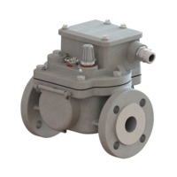
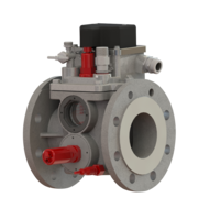
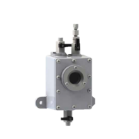
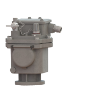
Monitoring relay for tap changers
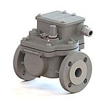
The monitoring relay for tap changers, also known as the protection relay for tap changers or oil flow relay, is a monitoring device for insulating liquid-filled tap changers with conservators. It protects the tap changer and the transformer from damage. The monitoring relay responds to excessive oil flow in the direction of the conservator and generates a signal disconnecting the tap changer and the transformer immediately from voltage supply.
The monitoring relay is suitable for open-air as well as indoor installation.
General
We provide more than 45 years experience in producing monitoring relays and other protection devices for liquid-cooled and liquid-insulated appliances. It ranks among the most distinguished manufacturers of this type of equipment.
EMB monitoring relays feature easy operation, high reliability and a very long life.
Our staff of highly qualified engineers and experienced skilled workers ensures top quality and highprecision products. The casings are machined on modern CNC controlled machine tools. All products are subjected to final inspection when all functions are checked using special test equipment.
Profound experience and expertise in this special field are a sound basis for high product quality. Extensive references from reputed tap changer and transformer manufacturers as well as other users are proof of the high qualitative level of the products.
DESIGN FEATURES
Casing
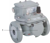
The casing is made of weather-resistant cast aluminium alloy provided with a paint coat. To check the switching system for proper function, the casing is provided with sightglasses arranged opposite each other and protected by hinged lids (1).
Cover
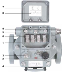
The cover is made of weather-resistant cast aluminium alloy provided with a paint coat. The upper section of the cover accommodates the terminal box (1). The test and reset key covered by a cap nut (2), a screw plug (3) or, alternatively on customer’s request, a bleeder valve (see section 9. „Explanation on code 97“) are arranged in front of the terminal box. In addition a plate (4) with instructions for actuating the test and reset key is arranged there. The terminal box (1) accommodates the earth terminal (5) and the bushings (6) for the terminals provided in the base of the cover. The terminal box is sealed by an aluminium cap (7) so that it is safe to touch and protected against pollution. If the cap is opened the graphic symbol and the connection diagram (8) are shown. The cable is inserted through the cable gland (9).
Function
The monitoring relay is installed in the pipe between the tap changer and the conservator as close as possible to the tap changer head. During normal operation of the tap changer gases are generated which are collected in the gas dome of the monitoring relay. If the gas volume exceeds the volume of the dome, the gas flows in the direction of the conservator.
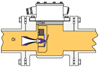
Fault: An incident causes an oil flow in the direction of the conservator.
Response: The liquid flow reaches the damper. If the flow rate exceeds the operating value of the
damper, the latter moves in flow direction.
This movement actuates a switch contact, and the tap changer and the transformer are
disconnected.
Technical data
| Parameter | Data | Notes |
|---|---|---|
| Voltage | AC 5 V - max. 250 V DC 5 V - max. 250 V | Note max. switching capacity |
| Current | AC 0,01 A - max. 6 A DC 0,01 A - max. 6 A | Cos φ > 0,5 L/R < 40 ms note max. switching capacity |
| Switching capacity | AC max. 1500 VA DC max. 1250 W | |
| Dielectric strength | AC 2500 V AC 2000 V (NO, NC) AC 1000 V (CO) | between electric circuit and earth between open contacts |
Temperature range:
|
| Climatic test acc. to others on request |
Temperature range:
| - 40 °C to +115 °C - 40 °F to +239 °F Up to + 135 °C requires version 21 | |
Temperature range:
| 1 mm²/s to 1100 mm²/s | |
| Insulating liquid | Mineral oil | Others on request |
| Resistance to vibration | Vibration: 2-200 Hz, 2 g Shock: 10 g, 11 ms | |
| Resistance to pressure | 0,25 MPa | |
| Resistance to vacuum | < 2,5 kPa | |
| Resistence to magnetic fields | 25 mT | Magnetic balance in any direction and polarity |
Switching system:
Response time of damper |
< 0,1 s |
|
| Cable gland | M20 × 1,5; M25 × 1,5 | Others on request |
| Nominal installation position | 2° to 4° | Ascending towards conservator |
| IP code | IP 56 | Others on request |
| Casing colour | 2-component texture paint | On polyurethane basis |
Options
Cable gland *
| Explanation | Code |
|---|---|
| M20x1.5: 1 cable gland and 1 dummy plug | 1 |
| M25x1.5: 1 cable gland and 1 dummy plug | 2 |
| M20x1.5: 2 cable glands | 3 |
| M20x1.5: 2 cable gland and 1 dummy plug (enclosed) | 3B |
| M25x1.5: 2 cable glands | 4 |
| M25x1.5: 2 cable gland and 1 dummy plug (enclosed) | 4B |
| 1/2“ NPT: 1 cable gland and 1 dummy plug | 6 |
| 1/2“ NPT: 2 cable glands | 7 |
| Cable gland: on customer’s request | 9 |
* Mandatory order data
Casing colour *
| Explanation | Code |
|---|---|
| Casing colour RAL 7001 (silver-grey) | 41 |
| Casing colour RAL 7012 (basalt-grey) | 42 |
| Casing colour RAL 7022 (umber-grey) | 43 |
| Casing colour RAL 7033 (cement-grey) | 44 |
| Casing colour RAL 7038 (agate-grey) | 45 |
| Casing colour RAL 7035 (light-grey) | 46 |
| Casing colour RAL 7016 (anthracite-grey) | 47 |
| Casing colour RAL 9002 (grey-white) | 48 |
| Casing colour RAL 7032 (siliceous-grey) | 49 |
* Mandatory order data
Equipment
| Explanation | Code |
|---|---|
| Metal name plate | 15 |
| With bleeder valve | 97 |
| With gasket (ÜRF 25/10-26 only) | 98 |
Special designs
Climate-proof version/IP code
| Explanation | Code |
|---|---|
| Climate-proof version (extreme frigid open-air conditions below - 40°C | 34 |
| Climate-proof version for offshore | 36 |
| IP 66 | 39 |
Insulating liquid
| Explanation | Code |
|---|---|
| Insulating liquid, silicone oil | 20 |
| Insulating liquid on ester basis | 21 |
Switching system
| Explanation | Code |
|---|---|
| Switching system equipped with two magnet contact tubes | 25 |
| Switching system equipped with three magnet contact tubes | 99 |
Customer's request
| Explanation | Code |
|---|---|
| Special request (as agreed with customer) | 29 |
Please contact us! We are glad to advise you and help with your selection.