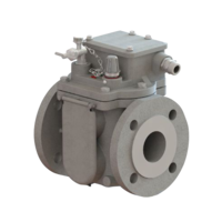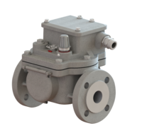
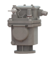
Gas relay
The gas relay can be used both on open-type transformers and hermetically sealed transformers. It responds to oil loss and gas accumulations that can occur as a result of faults in the transformer.
Mode of operation
Due to its specific design, the gas relay is suitable especially for hermetically sealed transformers without nitrogen cushion. Mounted on the transformer tank it can be filled completely through an oil filler so that reliable monitoring of the oil level is ensured.
An integral pressure switch (optional) and a temperature sensor offer significant additional monitoring options for the transformer.
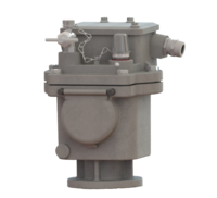
With open-type transformers with conservator the gas relay, on the one hand, serves as an air cell failure relay monitoring the hydro-type compensator (rubber sack) in the conservator and, on the other hand, the gas relay can also be used on the transformer cover.
During normal operation the gas relay must be filled completely with oil. Due to its boyant force the float is in the upper limit position.
As soon as gases are generated, these are collected in the gas relay and cause the float to descend. This actuates the switching contact (magnetic contact tube) and trips a signal.
Gas collection is indicated by the sightglass.
Technical Data
| Parameter | Data | Notes |
|---|---|---|
Temperature range:
|
| Climatic test acc. to Others on request |
Temperature range:
| - 40 °C to +115 °C - 40 °F to +239 °F Up to +135 °C design 21 required | |
Temperature range:
| 1 mm²/s to 1100 mm²/s | |
| Insulating liquid | Mineral oil | Others on request |
| Resistance to vibration | Vibration: 2-200 Hz, 1 g Shock: 25 g, 6 ms | Class 4M6 acc. to DIN EN 60721-3-4 |
| Resistance to pressure | 0,25 MPa | |
| Resistance to vacuum | < 2,5 kPa | |
| Insensitivity to magnetic fields | 25 mT | Static magnetic field of any direction and polarity |
Response of switching system to:
| 200 cm³ / 300 cm³ / 400 cm³ Tolerance ± 15% | Others on request |
| Cable gland | M20x1,5; M25x1,5 | Others on request |
| IP code | IP 56 | Others on request |
| Casing colour | Two-component texture paint | On polyurethane basis |
Options
Cable gland *
| Explanation | Code |
|---|---|
| M20x1.5: 1 Cable gland and 1 dummy plug | 1 |
| M25x1.5: 1 Cable gland and 1 dummy plug | 2 |
| M20x1.5: 2 Cable glands | 3 |
| M20x1.5: 2 Cable glands and 1 dummy plug (added loosely) | 3b |
| M25x1,5: 2 Cable glands | 4 |
| M25x1.5: 2 Cable glands and 1 dummy plug (added loosely) | 4b |
| M20x1.5: 1 Harting connector and 1 dummy plug | 5 |
| 1/2“ NPT: 1 Cable gland and 1 dummy plug | 6 |
| 1/2“ NPT: 2 Cable glands | 7 |
| Cable gland: On customer’s request | 9 |
* Mandatory order data
Casing colour *
| Explanation | Code |
|---|---|
| Casing colour RAL 9006 (white-aluminium) | 40 |
| Casing colour RAL 7001 (silver-grey) | 41 |
| Casing colour RAL 7012 (basalt-grey) | 42 |
| Casing colour RAL 7022 (umber-grey) | 43 |
| Casing colour RAL 7033 (cement-grey) | 44 |
| Casing colour RAL 7038 (agate-grey) | 45 |
| Casing colour RAL 7035 (light-grey) | 46 |
| Casing colour RAL 7016 (anthracite-grey) | 47 |
| Casing colour RAL 9002 (grey-white) | 48 |
| Casing colour RAL 7032 (siliceous-grey) | 49 |
* Mandatory order data
Casing
| Explanation | Code |
|---|---|
| Sealing of bleeding valve | 14 |
| Metal plate | 15 |
Special designs
Climate-proof version/IP code
| Explanation | Code |
|---|---|
| Climate-proof version for extreme frigid open-air conditions below - 40 °C | 34 |
| Climate-proof version for Offshore | 36 |
| Climate-proof version for aggressive industrial atmosphere | 36B |
| IP code 66 | 39 |
| IP code 67 | 39B |
Insulating liquid
| Explanation | Code |
|---|---|
| Insulating liquid silicone oil | 20 |
| Insulating liquid based on ester | 21 |
Switching system
| Explanation | Code |
|---|---|
| Switching system with two magnet contact tubes | 25 |
| Switching system with three magnet contact tubes | 99 |
Additional functions
| Explanation | Code |
|---|---|
| Temperature sensor | 61 |
Switching pressure from 20 kPa = 0,20 bar | 63B... 63B20 |
Special request
| Explanation | Code |
|---|---|
| Special request (on special agreement with customer) | 29 |
| Bleeding valve as mini ball valve | A |
| Large cap nut of test key, metal | B |
| Without hinged lids for sightglasses | C |
| With oil filler neck | D |
Please contact us! We are glad to advise you and help with your selection.