Buchholz relay BB 25
The type 22 (BB 25) of the Buchholz relays is especially used for rail vehicles. Find out more about this special type.
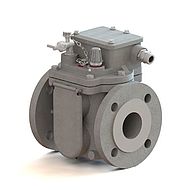
The Buchholz relay BB 25
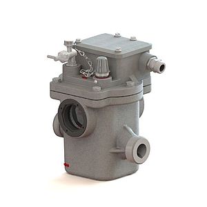
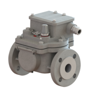
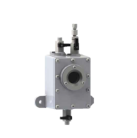
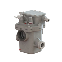
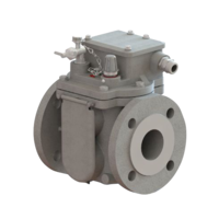
The Buchholz relay BB 25 was especially developed for use in rail vehicles and ensures operation free of interferences even with changing angles of inclination. In addition, the EMB Buchholz relays are ideally suited for the monitoring of traction transformers due to their high shock resistance.
The Buchholz relay BB 25 is installed in the pipe between the transformer tank and the conservator. During normal operation it is filled completely with insulating liquid. Due to buoyancy both floats of the Buchholz relay are at their top position.
In addition to the Buchholz relay type 22, the following types are also suitable for use in rail vehicles:
Function
The Buchholz relay BB 25 is installed in the pipe between the transformer tank and the conservator. During normal operation it is filled completely with insulating liquid. Due to buoyancy both floats of the Buchholz relay are at their top position.
If a fault occurs inside the transformer, the Buchholz relay responds as follows:
Gas accumulation
Fault: Free gas is available in the insulating liquid.
Response: The gas in the liquid moves upwards, accumulates in the Buchholz relay and displaces the insulating liquid level. As the liquid level falls, the upper float moves downwards. Movement of the upper float actuates a switch contact of the upper switching system so that an alarm signal is tripped. The lower float is not affected as from a certain gas volume the gas flows through a piping to the conservator.
Insulating liquid loss
Fault: Insulating liquid loss due to leakage.
Response: As the liquid level falls the top float moves downwards. An alarm is tripped. If the liquid loss continues, conservator and piping as well as the Buchholz relay will be emptied. As the liquid level falls, the lower float moves downwards. The moving lower float of the lower switching system actuates a switch contact so that the transformer is disconnected.
Insulating liquid flow
Fault: A spontaneous incident generates a pressure wave moving in the direction of the conservator.
Response: The liquid flow reaches the damper arranged in the liquid flow and held by a permanent magnet. If the flow rate exceeds the operating value of the damper, the latter moves in flow direction. Due to this movement a switch contact of the lower switching system is actuated so that the transformer is disconnected. After response the damper is locked and retained in this position even after reduction of the flow rate. Now the damper and, hence the lower switching system have to be unlocked by turning the test key anticlockwise.
Technical data
| Parameter | Data | Notes |
|---|---|---|
| Voltage | AC 5 V - max. 250 V DC 5 V - max. 250 V | |
| Current | AC 0,01 A - max. 6 A DC 0,01 A - max. 6 A | Cos φ > 0,5 L/R < 40 ms |
| Switching capacity | AC max. 1500 VA DC max. 1250 W | |
| Dielectric strength | AC 2500 V AC 2000 V (NO contact, NC contact) AC 1000 V (CO contact) | Between electric circuit and earth Between open contacts |
Temperature range:
|
| Climatic testing acc. to Others on request (Insulating liquid based |
Temperature range:
| - 40 °C to +115 °C - 40 °F to +239 °F till +135 °C requires code 21 | |
Temperature range:
| 1 mm²/s to 1100 mm²/s | |
| Insulating liquid | Mineral oil | Others on request |
| Resistance against vibration | Vibration: 2-200 Hz, 2 g | Acc. to class 4M6 following DIN EN 60721-3-4 |
| Resistance to pressure | 0,25 MPa | |
| Resistance to vacuum | < 2,5 kPa | |
| Insensitivity to magnetic fields | 25 mT | Static magnetic field of any direction and polarity |
Switching system:
Response time of damper |
< 0,1 s | More on request |
| Response of switching system in case of:
| 200 cm³ to 300 cm³ 01 = 0,65 ± 15% 02 = 1,00 ± 15% 03 = 1,50 ± 15% | |
| Cable gland | M20x1,5; M25x1,5 | Others on request |
| IP code | IP 56 | Others on request: IP 56, IP 66 |
| Casing colour | Two-component texture paint | On polyurethane basis |
Options
Cable gland *
| Explanation | Code |
|---|---|
| M20x1,5: 1 cable gland and 1 dummy plug | 1 |
| M25x1,5: 1 cable gland and 1 dummy plug | 2 |
| M20x1,5: 2 cable gland | 3 |
| M25x1,5: 2 cable glands | 4 |
| M20x1,5: 1 Harting connector and 1 dummy plug | 5 |
* Mandatory order data
Casing colour *
| Explanation | Code |
|---|---|
| Casing colour RAL 7001 (silver-grey) | 41 |
| Casing colour RAL 7012 (basalt-grey) | 42 |
| Casing colour RAL 7022 (umber-grey) | 43 |
| Casing colour RAL 7033 (cement-grey) | 44 |
| Casing colour RAL 7038 (agate-grey) | 45 |
| Casing colour RAL 7035 (light-grey) | 46 |
| Casing colour RAL 7016 (anthracite-grey) | 47 |
| Casing colour RAL 9002 (grey-white) | 48 |
| Casing colour RAL 7032 (siliceous-grey) | 49 |
* Mandatory order data
Equipment
| Explanation | Code |
|---|---|
| With oil drain plug (only double-float Buchholz relays) | 28 |
| With premounted Harting connector (The option is indicated by a letter after the code. For further information, please ask for special reference material.) | 59 |
Special designs
Climate-proof version/IP Code
| Explanation | Code |
|---|---|
| Climate-proof version for extreme frigid open-air conditions till - 40 °C | 34 |
| Climate-proof version for offshore | 36 |
| IP code 56 | 38 |
| IP code 66 | 39 |
Insulating liquid
| Explanation | Code |
|---|---|
| Insulating liquid silicone oil | 20 |
| Insulating liquid based on esther | 21 |
Switching system
| Explanation | Code |
|---|---|
| Lower switching system eqipped with two magnet contact tubes | 25 |
Special request
| Explanation | Code |
|---|---|
| Special request (on special agreement with customer) | 29 |
Please contact us! We are glad to advise you and help with your selection.